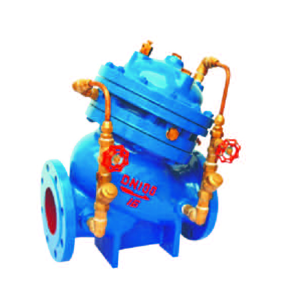
JD745X multifunctional pump control valve
- name: JD745X multifunctional pump control valve
- Type: JD745X
- Presure: 1.0~2.5MPa
- Specifications: DN50~DN1000
- material: Gray iron, ductile iron, carbon steel, etc.

Product description
Multifunctional pump control valve from the main valve and control valve and take over the system components, body with DC type valve, the main valve control room for diaphragm or piston type dual structure of the control room, control room than ordinary hydraulic control valve to increase a, an increase of the main valve control function, realized on the pump outlet opened slowly, full, slow closing, closing and other multi-function control, realized a valve, a regulation on the pump outlet multi-function control.
working principle:
When the pump starts, the water pressure acting on the main valve disc below and control room, the pressure to open the main valve, control room on the water through the cavity B slowly discharged to the outlet end, the main valve slowly open. Setting the opening of the regulating valve can be suitable for the opening speed of the landlord valve. When the water pump stops working, the inlet pressure decreased rapidly, in weight, spring pressure quickly shut down most of the opening, to prevent the backflow of water remaining open degree by controlling chamber cavity pressure and water pressure of the lower cavity under the combined action of slowly closed, closing speed slow down the formation of the buffer, to prevent the pressure surge.
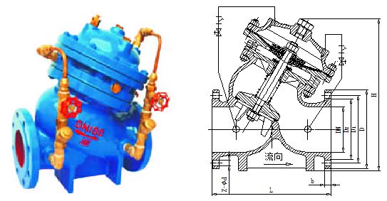
Main connection and outline dimensions(PN10)
nominal diameter
Main connection and outline dimensions(mm)
valve size mm
flange connection size mm
L
H
D
D1
D2
b
f
Z-Φd
50
203
293
165
125
93
18
3
4-Φ18
65
215
328
185
145
113
18
3
4-Φ18
80
248
364
200
160
128
20
3
8-Φ18
100
283
418
220
180
148
20
3
8-Φ18
125
330
481
250
210
178
22
3
8-Φ18
150
356
543
285
240
204
22
3
8-Φ22
200
444
673
340
295
259
24
3
8-Φ22
250
533
792
395
350
314
26
3
12-Φ22
300
600
927
445
400
362
26
4
12-Φ22
350
622
957
505
460
422
26
4
16-Φ22
400
698
1188
565
515
473
26
4
16-Φ26
450
775
1218
615
565
523
28
4
20-Φ26
Main connection and outline dimensions(PN16)
nominal diameter
Main connection and outline dimensions(mm)
valve size mm
flange connection size mm
L
H1
D
D1
D2
b
f
Z-Φd
50
203
293
165
125
93
18
3
4-Φ18
65
215
328
185
145
113
18
3
4-Φ18
80
248
364
200
160
128
20
3
8-Φ18
100
283
418
220
180
148
20
3
8-Φ18
125
330
481
250
210
178
22
3
8-Φ18
150
356
543
285
240
204
22
3
8-Φ22
200
444
673
340
295
259
24
3
12-Φ22
250
533
792
405
355
315
26
3
12-Φ26
300
600
927
460
410
370
28
3
12-Φ26
350
622
957
520
470
428
30
4
16-Φ26
400
698
1188
580
525
479
32
4
16-Φ30
450
775
1218
640
585
539
40
4
20-Φ30
Main parts material
Material code
Valve body, valve cover
The stem
valve seat
Sealing ring
the diaphragm
Spring
Z
HT200 gray cast iron
20Cr13
Gray cast iron
NR/NBR/EPDM/FEP/PFA
NR/NBR/EPDM/FEP/PFA
stainless steel
Q
QT450 nodular cast iron
20Cr13
nodular cast iron
C
WCB carbon steel
20Cr13
carbon steel
Other special materials, our company can also be tailored to customer needs.
Shell material
Shell applicable temperature(℃)
Housing applicable pressure MPa
Gray cast iron(Z type)
≤200
≤1.6
Nodular graphite cast iron(Q type)
≤350
≤4.0
Carbon steel(C type)
≤425
-
Sealing ring / diaphragm
Applicable medium
Applicable temperature(℃)
Natural rubber(NR)
hydrochloric acid, 30% sulfuric acid, 50% hydrofluoric acid, alkali, etc. 50%30% hydrochloric acid, sulfuric acid, hydrofluoric acid, alkali, etc.
≤85
Nitrile rubber (NBR)
Water, oil, waste gas and waste liquid pollution, etc.
≤150
Ethylene propylene rubber (FPDM)
In addition to salt water, 40% boron water, 5%~15% nitric acid and sodium hydroxide, etc..
≤120
Poly (ethylene propylene) plastics(FEP)
In addition to the molten alkali metals, fluorine and aromatic hydrocarbons hydrochloric acid, sulfuric acid, aqua regia, organic acid, strong oxidizing agents, concentrated and dilute acid alternate, alternating alkaline and various organic solvents
≤150
Fusible polytetrafluoroethylene(PFA)
≤180
Nominal pressure PN(MPa)
shell(MPa)
Test pressure(MPa)
Seal (liquid)
Seal (gas)
1.0
1.5
1.1
0.6
1.6
2.4
1.76
0.6
- Implementation standards
Design specification: JB/T10674
Structure length: JB/T10674, GB/T 12221
Connecting flange: GB/T9113, HG/T20592, HG/T20615, JB/T 79
Experiment and test: GB/T13927, JB/T 9092
Pressure temperature: GB/T 17241.7, GB/T12224
Product identification: GB/T 12220
- Valve maintenance
(1) the engineering application of the hydraulic control valve is a manufacturing plant inspection, a variety of complete, technical information to meet the requirements of the product.
(2) the nominal pressure of the valve has different levels, the pipeline transportation of the media, the working pressure should be less than the value of the valve nominal pressure.
(3) the project of the hydraulic control valve setting should have enough space for management, operation, installation and maintenance, and should meet the requirements of the pipeline valve.
(4) when the pipe is connected by flange, the hydraulic control valve with flange connection should be adopted, and the hydraulic control valve with groove connection should be adopted when the pipeline is connected with a groove.
(5) the hydraulic control valve should be set on the one-way flow of media in the pipeline.
(6) the direction of the arrow on the main body of the hydraulic control valve must be consistent with the direction of the pipeline system.
(7) the water control valve should not have gas blocking, air resistance. Automatic exhaust valve should be set at the highest position of the pipe network.
(8) when the valve is installed, the valve cover and valve stem should be facing up. Vertical installation, valve cover, valve stem should be outward.
(9) the valve should be done before the installation of strength and tightness test.