The product description
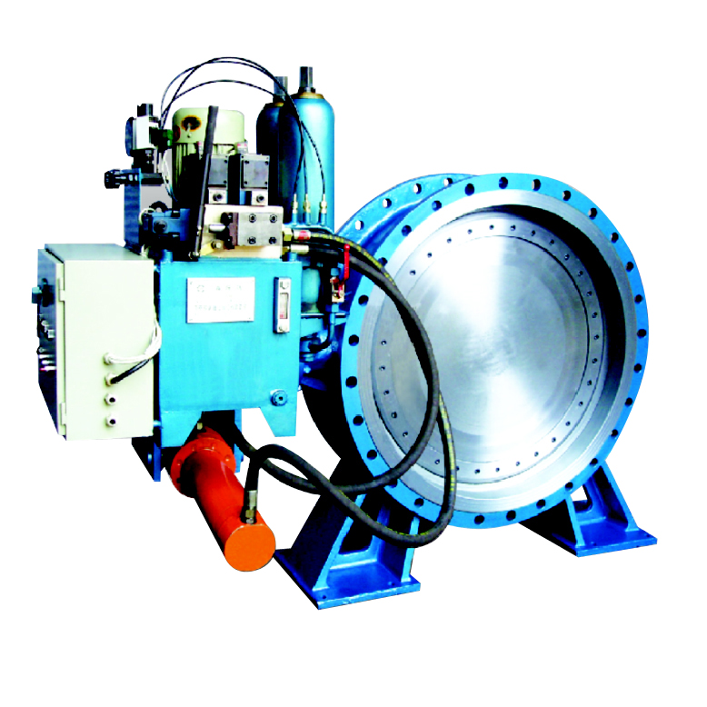
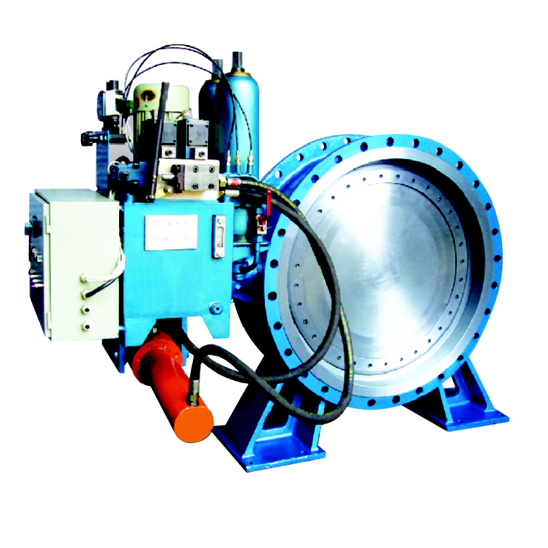
Energy storage tank type hydraulic control slow close check butterfly valve is our factory in digesting and absorbing foreign hydraulic control valve based on the latest development of new products. At present, the valve is the latest generation of hydraulic control butterfly valve in our country, it has both the function of the gate valve and check valve, is a kind of can according to the setting in advance good program, two stages (fast clearance Angle, and then slowly closed rest Angle) closed action to eliminate water hammer in pipeline damage their ideal control system.
Structural characteristics of
This product is mainly composed of butterfly valve body, transmission device, hydraulic and electrical control part of the group. Has the following main features:
A. environmental protection products in the valve cavity through the water using harmless to human body health and safety and environmentally friendly coatings, in drinking water sanitation standard, the medium in pipeline doesn't create any pollution.
B. conventional type product in the valve cavity through the water the adhesion of anticorrosion coatings. This valve seal form is divided into two kinds, the first form is: stainless steel, stainless steel, and USES the three eccentric structure of its sealing performance and reliable butterfly plate shut tight, easy to release; Seal adopt stainless steel, corrosion resistant wear long service life, convenient maintenance, after the valve with long steel rubber, it USES a leak, only need to replace the sealing ring; Bearing for lead-free no oil self-lubricating bearing has a carrying capacity is strong, good wear resistance, low friction resistance and other characteristics; Shaft end seal USES self-tightening type such as double seal, the sealing effect is good. Butterfly plate plastic adopts streamline design, small flow resistance coefficient (< 0.2), the valve strength, good rigidity, body strength test can withstand twice the nominal pressure. Has the characteristics of novelty, beautiful shape.
This valve has a perfect hydraulic system and electric control system, as well as on-site operation, also can remote operation, but this valve control system USES the storage tank to replace the present domestic several valve factory in the production of hydraulic control butterfly valve with a heavy hammer hammer, hammer potential energy into hydraulic energy, not only save the long running bearing weight of energy consumption, improved the hydraulic pressure performance of the system to avoid the runtime maintenance personnel casualty accidents and mental insecurity and fear, and its control mechanism design is novel, reasonable design, small volume, light weight, simple structure, complete functions, movements flexible and reliable, beautiful appearance, energy saving material, convenient maintenance, and do not need to stop the pump when maintenance work and so on. To easily realize pump valve interlocking program control and microcomputer centralized control, power failure, shaking the manual oil pump can close the valve. The valve open and close, the movement is very convenient. This valve hydraulic and electric control parts be separated from the valve installed, according to whether the hydraulic and electrical separation and two kinds of forms, user can choose according to the situation.
The working principle of
Hydraulic system power supply electrical units, there are three kinds of oil pump accumulator hydraulic energy storage, manual oil pump, which stored in accumulator hydraulic can give priority to power supply, pump unit is responsible for the accumulator charging, when need can also direct drive valve switch, manual oil pump used in the accumulator, in the absence of any stored energy without electricity manual switch valve. To lose electric valve type hydraulic system, the two solenoid valve electromagnet to when the valve opens at the same time, the loss of electricity at the same time the valve closed. For electric valve type hydraulic system, an electromagnetic valve electromagnet electric valve opens, the other electromagnetic valve electromagnet closed electric valve. Open valve speed regulation by integrated block throttle valve; In two stages, automatically shut off the valve closed fast first is about 65 ℃, and then slowly closed left about 25 ℃, fast closing speed and Angle in the cylinder backend device regulation. In the case of without electricity or need to manually, by artificial push electromagnetic valve valve core, make the oil in the corresponding state, shaking the manual oil pump, can open or close the valve.
The main connection and shape size
nominal size
The main valve connection size mm
valve connection size mm
flange connection size mm
DN
L
H
H1
H2
H3
H4
H5
H6
L1~L5
n-d
A1
A2
D
K
D0
b
N-Φ
300
178
310
575
285
220
670
540
816
According to the
The guest
households
650
1200
440
395
363
24
12-23
350
190
320
605
317
220
670
540
816
650
1200
490
445
413
26
12-23
400
216
340
640
345
220
720
540
912
700
1400
540
495
463
28
16-23
450
222
370
670
373
220
720
540
912
700
1400
595
550
518
28
16-23
500
229
400
735
400
240
720
540
912
700
1400
645
600
568
30
20-23
600
267
460
800
459
240
720
610
912
700
1400
755
705
667
30
20-26
700
292
540
856
520
240
825
610
1095
800
1600
860
810
772
32
24-26
800
318
580
990
578
310
825
610
1095
800
1600
975
920
878
34
24-31
900
330
635
1039
655
310
825
610
1095
800
1600
1075
1020
978
36
24-31
1000
410
695
1089
718
310
825
610
1095
800
1600
1175
1120
1078
36
28-31
1200
470
810
1219
845
310
825
610
1095
800
1600
1375
1320
1280
30
32-30
1400
530
920
1329
975
360
855
610
1329
800
1800
1575
1520
1480
30
36-30
1600
600
1040
1479
1100
360
855
610
1329
800
1800
1790
1730
1690
32
40-30
1800
670
1140
1650
1240
360
855
610
1329
800
1800
1990
1930
1890
34
44-30
2000
760
1250
1800
1359
525
895
810
1234
900
1800
2190
2130
2090
34
48-30
2200
590
1360
1979
1500
525
940
810
1234
900
1800
2405
2340
2295
36
52-33
The main connection and shape size PN6
主要阀门连接尺寸mm
阀门连接尺寸mm
法兰连接尺寸mm
DN
L
H
H1
H2
H3
H4
H5
H6
L1~L5
n-d
A1
A2
D
K
D0
b
N-Φ
300
178
310
575
285
220
670
540
816
根
据
客
户
需
求
定
做
650
1200
440
395
363
24
12-23
350
190
320
605
317
220
670
540
816
650
1200
490
445
413
26
12-23
400
216
340
640
345
220
720
540
912
700
1400
540
495
463
28
16-23
450
222
370
670
373
220
720
540
912
700
1400
595
550
518
28
16-23
500
229
400
735
400
240
720
540
912
700
1400
645
600
568
30
20-23
600
267
460
800
459
240
720
540
912
700
1400
755
705
667
30
20-26
700
292
540
856
520
240
825
610
1095
800
1600
860
810
772
32
24-26
800
318
580
991
578
310
825
610
1095
800
1600
975
920
878
34
24-31
900
330
635
1039
655
310
825
610
1095
800
1600
1075
1020
978
36
24-31
1000
410
695
1089
718
310
825
610
1095
800
1600
1175
1120
1078
36
28-31
1200
470
810
1239
845
360
855
610
1329
800
1800
1405
1340
1295
40
32-34
1400
530
920
1359
975
360
855
610
1329
800
1800
1630
1560
1510
44
36-37
1600
600
1040
1513
1100
525
895
810
1234
900
1800
1830
1760
1710
48
40-37
1800
670
1140
1655
1240
525
895
810
1234
900
1800
2045
1970
1918
50
44-40
2000
760
1250
1843
1359
680
895
810
1234
900
1800
2265
2180
2125
54
48-43
主要连接及外形尺寸PN10
公称
通径
主要阀门连接尺寸mm
阀门连接尺寸mm
法兰连接尺寸mm
DN
L
H
H1
H2
H3
H4
H5
H6
L1~L5
n-d
A1
A2
D
K
D0
b
N-Φ
300
178
310
630
285
220
670
540
816
根
据
客
户
需
求
定
做
650
1200
445
400
370
28
12-23
350
190
320
643
317
220
670
540
816
650
1200
505
460
429
30
16-23
400
216
340
660
345
240
720
540
912
700
1400
565
515
480
32
16-28
450
222
370
710
380
240
720
540
912
700
1400
615
565
530
32
20-28
500
229
400
720
425
240
720
540
912
700
1400
670
620
582
34
20-28
600
267
460
795
469
240
720
540
912
700
1400
780
725
682
36
20-31
700
292
540
910
530
310
825
610
1095
800
1600
895
840
794
40
24-31
800
318
580
980
590
310
825
610
1095
800
1600
1015
950
901
44
24-34
900
330
635
1050
665
310
825
610
1095
800
1600
1115
1050
1001
46
28-34
1000
410
695
1107
718
360
895
610
1329
800
1600
1230
1160
1112
50
28-37
1200
470
810
1150
855
360
895
610
1329
800
1600
1455
1380
1328
56
32-40
1400
530
920
1413
1000
525
940
810
1234
900
1800
1675
1590
1530
62
36-43
1600
600
1040
1618
1130
680
940
810
1234
900
1800
1915
1820
1750
68
40-49
1800
670
1140
1758
1250
680
940
810
1234
900
1800
2115
2020
1950
70
44-49
2000
760
1250
1960
1359
680
940
810
1234
900
1800
2325
2230
2150
74
48-49
-
Main parts material
material code
Valve body, valve cover, valve plate
valve seat
sealing ring
valve stem
filler
Q
QT450 Nodular graphite cast iron
Q450+Copper / stainless steel
Stainless steel multi layer / rubber
20Cr13
graphite
C
WCB carbon steel
WCB+Copper / stainless steel
Stainless steel multi layer / rubber
20Cr13
graphite
-
Nickel chromium cast iron
Nickel chromium cast iron + stainless steel
rubber
316L
graphite
Other special materials, our company can also be tailored to customer needs.
-
Main performance characteristics
Shell material
Applicable medium
Hard seal temperature(℃)
soft seal temperature(℃)
Nodular graphite cast iron(Q)
Water, air, oil
≤425
≤80
carbon steel(C type)
Water, air, oil
≤425
≤80
Nickel chromium cast iron
seawater
-
≤80
Nominal pressure PN(MPa)
shell
test pressure(MPa)
seal(liquid)
seal(gas)
0.25
0.375
0.275
0.6
0.6
0.9
0.66
0.6
1.0
1.5
1.1
0.6
1.6
2.4
1.8
0.6
Special parameter
Valve opening time (SEC)
Valve diameter
Adjustable
<1000
≥1000
10~60
30~120
Valve angle (degree)
Quick closing
65±10
slow closing
25±10
Valve time (degree)
Quick closing
2~25
3~30
slow closing
4~60
5~60
- Implementation standards
Design specification: JB/T 5299, JB/T 8527
Structure length: GB/T 12221
Connecting flange: GB/T 17241.6, 7005-2 BS, PrEN1092-2 ISO
Experiment and test: GB/T13927, JB/T 9092
Pressure temperature: GB/T 9131
Product identification: GB/T 12220
- Storage and maintenance
Products for a long time, should be placed in a dry place, closed at both ends of the import and export, in the sealing surface coated with anti rust oil. When the temporary parking can be added in the external wall plate auxiliary support to maintain a smooth. The first half is not installed, the hydraulic system for cleaning oil. This valve is prohibited open storage.
Installation and maintenance
Before installation should check the valve nameplate parameter meets the use requirements; cleaning the channel of the valve body and disc, check each part have no damage phenomenon and parts of the bolt is fastened. If the valve is installed in the outlet of the pump, the direction of the valve body to seal the direction of the pressure, and the direction of the water pump in the opposite direction; butterfly valve installed on the basis of the level should be corrected to ensure that the valve shaft does not tilt. Valve supporting feet and auxiliary support is mainly used to ensure the valve installation smooth operation, not a lot of bear perpendicular to the pipe axial water thrust; lifting may not flip, upside down; pay attention to the four lifting points to select the position of equilibrium.
More Products


