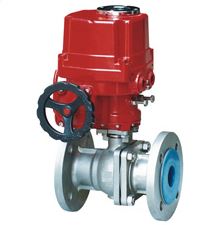
ball valveQ941
- name: ball valveQ941
- Type: Q941
- Presure: 1.0~10.0MPa
- Specifications: DN50~DN800
- material: WCB CF8 CF3 CF8M CF3M

Product description
The electric ball valve is provided with the same rotating 90 degree lifting action, with a circular through hole or a channel through its axis. The ratio of the spherical surface and the channel port should be such that when the ball is rotated 90 degrees, the inlet and outlet should be all spherical, thereby cutting off the flow. Electric ball valves only need a very small torque can be closed tight. Full equality of the inner cavity of the valve body to provide a very small resistance, through the flow channel. It is generally considered the most suitable for direct use, but the recent development has been designed so that it has a throttle and control flow. Electric ball valve is now in the oil, natural gas, medicine, food, water and electricity, nuclear power, electricity, water supply and drainage, heating, metallurgy and other industries to be widely used, is the key to the construction of national defense machinery products. It occupies a lot in the market share, mainly because the electric ball valve strong function, small volume, reliable performance, flow capacity, light and pleasant, remote control, such as a variety of reasons, electric ball valve is not only throttle, cut-off, cutting, breaking, good products or flow regulating system of preferred products.
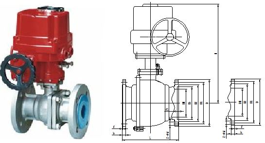
Main connection and dimensions(PN16)
nominal diameter
Main valve connection dimensions
Valve connection size
Flange connection size
L
H
D
D1
D2
b
f
Z-Φd
25
150
360
115
85
65
14
2
4-Φ14
32
165
390
135
100
78
16
2
4-Φ18
40
180
395
145
110
85
16
3
4-Φ18
50
200
405
160
125
100
16
3
4-Φ18
65
220
490
180
145
120
18
3
4-Φ18
80
250
595
195
160
135
20
3
8-Φ18
100
280
640
215
180
155
20
3
8-Φ18
125
320
695
245
210
185
22
3
8-Φ18
150
360
740
280
240
210
24
3
8-Φ23
200
400
800
335
295
265
26
3
12-Φ23
250
550
880
405
355
320
30
3
12-Φ25
Main connection and dimensions(PN25)
nominal diameter
Main valve connection dimensions
Valve connection size
flange connection size
L
H
D
D1
D2
b
f
Z-Φd
25
150
360
115
85
65
16
2
4-Φ14
32
165
390
135
100
78
18
2
4-Φ18
40
180
395
145
110
85
18
3
4-Φ18
50
200
405
160
125
100
20
3
4-Φ18
65
220
490
180
145
120
22
3
8-Φ18
80
250
595
195
160
135
22
3
8-Φ18
100
280
640
230
190
160
24
3
8-Φ23
125
320
695
270
220
188
28
3
8-Φ25
150
360
740
300
250
218
30
3
8-Φ25
200
400
800
360
310
278
34
3
12-Φ25
250
550
880
425
370
332
36
3
12-Φ30
Main connection and dimensions(PN40)
nominal diameter
Main valve connection dimensions
Valve connection size
flange connection size
L
H
D
D1
D2
D6
b
f
f2
z-Φd
25
150
360
115
85
65
58
16
2
4
4-Φ14
32
180
390
135
100
78
66
18
2
4
4-Φ18
40
200
395
145
110
85
76
18
3
4
4-Φ18
50
220
405
160
125
100
88
20
3
4
4-Φ18
65
250
490
180
145
120
110
22
3
4
8-Φ18
80
280
595
195
160
135
121
22
3
4
8-Φ18
100
320
640
230
190
160
150
24
3
4
8-Φ23
125
400
695
270
220
188
176
28
3
4.5
8-Φ25
150
400
740
300
250
218
204
30
3
4.5
8-Φ25
200
550
800
375
320
282
260
38
3
4.5
12-Φ30
Main connection and dimensions(PN64)
nominal diameter
Main valve connection dimensions
Valve connection size
Flange connection size
L
H
D
D1
D2
D6
b
f
f2
z-Φd
25
216
360
135
100
78
58
22
2
4
4-Φ18
32
229
390
150
110
82
66
24
2
4
4-Φ23
40
241
395
165
125
95
76
24
3
4
4-Φ23
50
292
405
175
135
105
88
26
3
4
4-Φ23
65
330
490
200
160
130
110
28
3
4
8-Φ23
80
356
595
210
170
140
121
30
3
4
8-Φ23
100
432
640
250
200
168
150
32
3
4.5
8-Φ25
125
508
695
295
240
202
176
36
3
4.5
8-Φ30
150
559
740
340
280
240
204
38
3
4.5
8-Φ34
200
660
800
405
345
300
260
44
3
4.5
12-Φ34
Main parts material
Soft seal
material code
valve body
ball body
valve stem
sealing ring
filler
shim
C
WCB carbon steel
20Cr13
20Cr13
PTFE/PPL
graphite
304+graphite
P
CF8 (304 )stainless steel
304
304
PTFE/PPL
PTFE/PPL
PTFE/PPL
PL
CF3 (304 L) stainless steel
304L
304L
PTFE/PPL
PTFE/PPL
PTFE/PPL
R
CF8M (316) stainless steel
316
316
PTFE/PPL
PTFE/PPL
PTFE/PPL
RL
CF3M(316L)stainless steel
316L
316L
PTFE/PPL
PTFE/PPL
PTFE/PPL
hard seal
material code
valve body
ball body
valve stem
valve seat filler
shim
C
WCB carbon steel
20Cr13+Nickel based alloy / tungsten cobalt alloy
20Cr13
20Cr13+Cemented carbide
graphite
304+graphite
P
CF8 (304 )stainless steel
304+Nickel based alloy / tungsten cobalt alloy
304
304+Cemented carbide
graphite
304+graphite
PL
CF3 (304 L) stainless steel
304L+Nickel based alloy / tungsten cobalt alloy
304L
304L+Cemented carbide
graphite
304+graphite
R
CF8M (316) stainless steel
316+Nickel based alloy / tungsten cobalt alloy
316
316+Cemented carbide
graphite
304+graphite
RL
CF3M(316L)stainless steel
316L+Nickel based alloy / tungsten cobalt alloy
316L
316L+Cemented carbide
graphite
304+graphite
Other special materials, our company can also be tailored to customer needs.
Shell material
Applicable medium
Applicable temperature(℃)
remarks
WCB(C type)
Water, steam, oil
≤150
When the sealing ring for PPL
≤280℃
CF8(P type)
Nitric acid
≤150
CF8M(R type)
Acetic acid
≤150
CF3(PL type )
Strong oxidizing medium
≤150
CF3M(RL type)
Urea and other corrosive media
≤150
Shell material
Applicable medium
Applicable temperature(℃)
WCB(C type)
Water, steam, oil
≤425
CF8(P type)
Nitric acid
≤540
CF8M(R type)
Acetic acid
≤540
CF3(PL type)
Strong oxidizing medium
≤425
CF3M(RL type)
Urea and other corrosive media
≤425
nominal diameter PN(MPa)
shell(MPa)
test pressure(MPa)
sealing(liquid)(MPa)
sealing(gas)(MPa)
1.6
2.4
1.8
0.6
2.5
3.8
2.8
0.6
4
6
4.4
0.6
6.4
9.6
7
0.6
- Implementation standards
Design specification: GB/T 12237
Structure length: GB/T 12221
Connecting flange: GB/T9113, HG/T20592, HG/T20615, JB/T 79
Experiment and test: GB/T13927, JB/T 9092
Pressure temperature: GB/T 9131
Product identification: GB/T 12220
- Storage and maintenance:
1 valves should be stored in a dry and ventilated place. The application of lid port channel.
2 long-term storage of the valve should be regularly checked and cleaned, in particular, to clean the surface of the valve seat sealing surface to prevent damage.
3 if stored for more than 18 months, the valve should be tested before installation, and make a good record.
4 electric valve repair and assembly, the sealing performance test should be carried out.
Installation and maintenance:
1 before installation to confirm the valve identification (such as models, nominal diameter, nominal pressure, material) is based on the requirements of the pipeline system identification.
2 carefully check the valve's channel and sealing surface before installation. If you have any goods, shall be cleaned.
3 before installation, make sure that all the bolts are tightened.
4 before installation, make sure the packing is pressed.