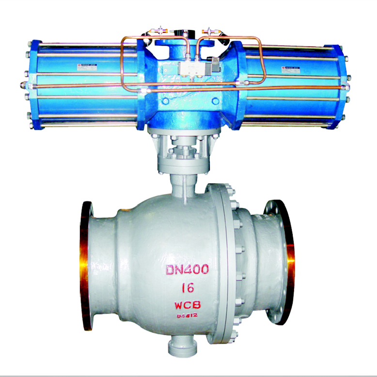
Q647 Pneumatic fixed ball valve
- name: Q647 Pneumatic fixed ball valve
- Type: Q647
- Presure: 1.0~4.0MPa
- Specifications: DN50~DN500
- material: WCB、CF8、CF8M、A4,etc.


Product description
Pneumatic type fixed ball valve is a new generation of high-performance ball valve, suitable for long-distance pipelines and general industrial pipeline, the strength and safety, resistance to harsh environments and so in the design were special consideration, applicable to various corrosive and non corrosive media. It is compared with the floating ball, work force of fluid pressure before the valve resulting in the ball on the all pass to the bearing, will not make the ball move to the seat, so the seat small deformation, stable sealing performance, long service life, suitable for high pressure, large diameter occasions. Advanced spring pre - seat assembly, with self - tightening characteristics, to achieve the upper seal. Each valve has two seats, each direction can be sealed and thus the installation is not limited to the flow, is a two-way.
Main connection and dimensions PN16
DN
Main connection dimensions
Main body size
Flange connection size
L
H
H1
D
D1
D2
d
f
Z-Φd
50
216
102
274
165
125
100
18
3
4-18
65
241
114
379
185
145
120
18
3
4-18
80
283
127
389
200
160
135
20
3
8-18
100
305
152
479
220
180
155
20
3
8-18
125
356
184
552
250
210
185
22
3
8-18
150
394
219
666
285
240
210
22
3
8-23
200
457
273
736
340
295
265
24
3
12-23
250
533
360
926
405
355
320
26
3
12-26
300
610
395
1059
460
410
375
28
4
12-26
350
686
430
1127
520
470
435
30
4
16-26
400
762
470
1393
580
525
485
32
4
16-30
450
864
550
1468
640
585
545
40
4
20-30
500
914
580
1538
715
650
608
44
4
20-33
600
1067
700
1370
840
770
718
54
5
20-36
700
1245
800
1450
910
840
788
58
3
24-36
Main connection and dimensions PN25
DN
Main connection dimensions
Main body size
Flange connection size
L
H
H1
D
D1
D2
d
f
Z-Φd
50
216
102
340
165
125
100
20
3
4-18
65
241
114
379
185
145
120
22
3
8-18
80
283
127
452
200
160
135
24
3
8-18
100
305
152
479
235
190
160
24
3
8-23
125
381
184
646
270
220
188
26
3
8-26
150
403
219
666
300
250
218
28
3
8-26
200
502
273
814
360
310
278
30
3
12-26
250
568
360
1002
425
370
332
32
3
12-30
300
648
395
1059
485
430
390
34
4
16-30
350
762
430
1150
555
490
448
38
4
16-34
400
838
470
1205
620
550
505
40
4
16-36
450
914
550
1250
670
600
555
46
4
20-36
500
991
580
1295
730
660
610
48
4
20-36
600
1143
700
1390
845
770
718
58
5
20-39
700
1346
800
1470
960
875
815
60
3
24-42
Main connection and dimensions PN40
DN
main connection size
Main body size
Flange connection size
L
H
H1
D
D1
D2
D6
d
f
f1
Z-Φd
50
216
102
405
165
125
100
88
20
3
4.5
4-18
65
241
114
405
185
145
120
110
22
3
4.5
8-18
80
283
127
574
200
160
135
121
24
3
4.5
8-18
100
305
152
574
235
190
160
150
24
3
5
8-23
125
381
184
756
270
220
188
176
26
3
5
8-26
150
403
219
756
300
250
218
204
28
3
5
8-26
200
502
273
1060
375
320
282
260
34
3
5
12-30
250
568
360
1060
450
385
345
313
38
3
5
12-34
300
648
395
1060
515
450
408
364
42
4
5
16-34
350
762
430
1360
580
510
465
422
46
4
5.5
16-36
400
838
470
1360
660
585
535
474
50
4
5.5
16-39
450
914
550
2840
685
610
560
524
57
4
5.5
20-39
500
991
580
2840
755
670
612
576
57
4
5.5
20-42
600
1143
700
3300
890
795
730
678
72
5
5.5
20-48
Main connection and dimensions PN64
DN
Main connection dimensions
body connection sizes flange connection sizes
L
H
H1
D
D1
D2
D6
d
f
f1
Z-Φd
50
292
114
340
180
135
100
88
26
3
4.5
4-23
65
330
124
-
205
160
130
110
26
3
4.5
8-23
80
356
133
-
215
170
140
121
28
3
4.5
8-23
100
406
159
479
250
200
168
150
30
3
5
8-26
150
495
250
666
345
280
240
204
36
3
5
8-33
200
597
295
895
415
345
300
260
42
3
5
12-36
250
673
395
1002
470
400
352
313
46
3
5
12-36
300
762
445
1059
530
460
412
364
52
4
5
16-36
350
826
500
1160
600
525
475
422
56
4
5.5
16-39
400
902
530
1250
670
585
525
474
60
4
5.5
16-42
Main parts material
Soft seal
Material code
valve body
sphere
The stem
Sealing ring
filler
shim
C
WCB carbon steel
20Cr13
20Cr13
PTFE/PPL
graphite
304+graphite
P
CF8 (304 )stainless steel
304
304
PTFE/PPL
PTFE/PPL
PTFE/PPL
PL
CF3 (304 L) stainless steel
304L
304L
PTFE/PPL
PTFE/PPL
PTFE/PPL
R
CF8M (316)stainless steel
316
316
PTFE/PPL
PTFE/PPL
PTFE/PPL
RL
CF3M(316L)stainless steel
316L
316L
PTFE/PPL
PTFE/PPL
PTFE/PPL
hard seal
Material code
valve body
sphere
The stem
Sealing ring
filler
shim
C
WCB carbon steel
20Cr13+Nickel based alloy / tungsten cobalt alloy
20Cr13
20Cr13+Cemented carbide
graphite
304+graphite
P
CF8 (304 )stainless steel
304+Nickel based alloy / tungsten cobalt alloy
304
304+Cemented carbide
graphite
304+graphite
PL
CF3 (304 L) stainless steel
304L+Nickel based alloy / tungsten cobalt alloy
304L
304L+Cemented carbide
graphite
304+graphite
R
CF8M (316) stainless steel
316+Nickel based alloy / tungsten cobalt alloy
316
316+Cemented carbide
graphite
304+graphite
RL
CF3M(316L)stainless steel
316L+Nickel based alloy / tungsten cobalt alloy
316L
316L+Cemented carbide
graphite
304+graphite
Other special materials, our company can also be tailored to customer needs.
- Implementation standards
Design specification: GB/T 12237
Structure length: GB/T 12221
Connecting flange: GB/T9113, HG/T20592, HG/T20615, JB/T 79
Experiment and test: GB/T13927, JB/T 9092
Pressure temperature: GB/T 9131
Product identification: GB/T 12220
- Valve maintenance
1. To ensure the pneumatic pipe valve installation location of the pipeline in the coaxial position and line two flanges should be maintained in parallel and confirm the pipelines can be under pneumatic pipe valve of its own weight. If it is found that the pipeline is not under pneumatic pipe valve weight, before installation pipeline is equipped with the corresponding support.
2 to confirm whether there are impurities in the pipeline, welding slag, etc., must be cleaned inside the pipeline purge.
3. Check the gas dynamic pipeline valve plate, and the gas dynamic pipeline ball valve fully open all closed several operations, confirmed the valve to work properly, and comprehensive inspection once all the details of the valve to ensure the valve intact.
4 remove the protective cover at both ends of the valve, check valve body is clean, clean body cavity, as a result of pneumatic pipe valve sealing surface is the ball shape, even if the tiny debris may also cause damage to the sealing surface.
5 pneumatic pipe ball valve flange and pipe flange between the pipeline design requirements for the installation of the sealing gasket.
6 bolts on the flange to be symmetrical, successive, uniform tightening.
7 after the installation is completed, start pneumatic valve open and close several times, it should be flexible, uniform force, pneumatic pipe ball valve working properly.