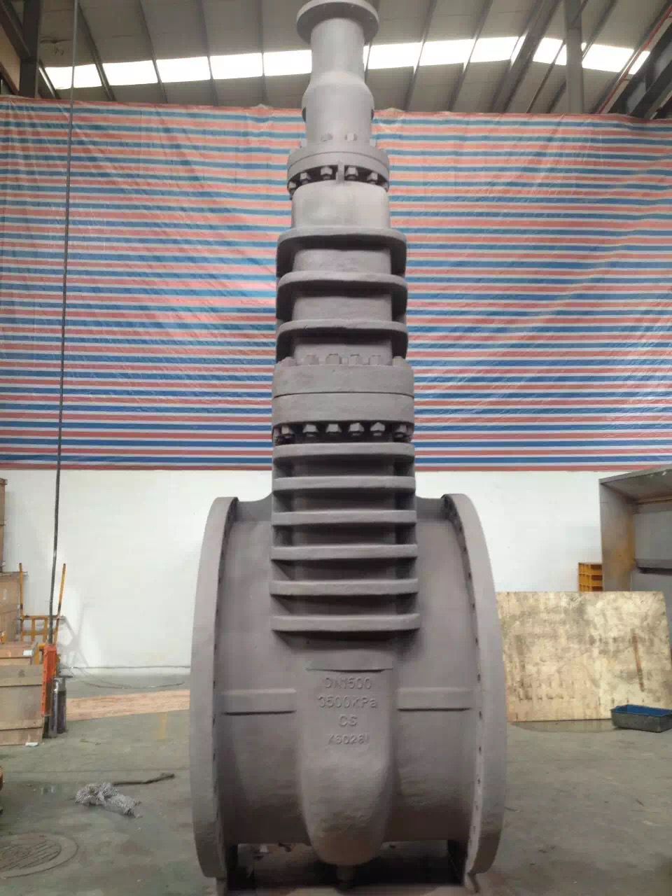
Oxygen globe valve YJ41
- name: Oxygen globe valve YJ41
- Type: YJ41
- Presure: 1.6~4.0MPa
- Specifications: DN15~DN400
- material: Silicon brass, stainless steel, cast steel

- Product description
Oxygen specific cut-off valve is made of silicon brass or stainless steel casting material, with high mechanical strength, wear resistance, good safety and so on. Used in the oxygen pipeline, with the best anti explosion flame retardant performance, eliminating the safety factors on the oxygen pipeline. The oxygen valve is forced to seal the valve, so when the valve is closed, the valve must be applied to the valve pressure to force the sealing surface does not leak. Oxygen valve is a kind of special valve of the oxygen pipe network. Stood in the city of liquefied petroleum gas reserves, the oxygen valve is also used in refinery, petroleum chemical plant, petrochemical plant of liquefied gas system, as a control device for opening and closing the closure of media.
Main connection and dimensions(PN16)
nominal diameter
Main dimensions and connection dimensions(mm)
Valve connection size
flange connection size
L
H
D0
D
D1
D2
b
f
z-Φd
25
160
305
160
115
85
57
18
2
4-14
32
180
316
160
140
100
68
18
2
4-18
40
200
328
180
150
110
76
18
3
4-18
50
230
356
200
165
125
91
18
3
4-18
65
290
389
280
185
145
111
18
3
4-18
80
310
400
280
200
160
126
20
3
8-18
100
350
460
320
220
180
146
20
3
8-18
125
400
528
320
250
210
176
22
3
8-18
150
480
668
450
285
240
201
22
3
8-23
200
600
795
500
340
295
256
24
3
12-23
250
650
910
560
405
355
312
26
3
12-27
300
750
1200
640
460
410
365
28
4
12-27
350
850
1200
720
520
470
425
30
4
16-27
400
950
1560
800
580
525
477
32
4
16-30
Main connection and dimensions(PN25)
nominal diameter
Main dimensions and connection dimensions(mm)
Valve connection size
flange connection size
L
H
D0
D
D1
D2
b
f
z-Φd
25
160
275
160
115
85
57
18
2
4-14
32
180
280
180
140
100
68
18
2
4-18
40
200
330
200
150
110
76
18
3
4-18
50
230
350
240
165
125
91
20
3
4-18
65
290
355
280
185
145
111
22
3
8-18
80
310
400
280
200
160
126
24
3
8-18
100
350
415
320
235
190
151
24
3
8-23
125
400
460
360
270
220
177
26
3
8-27
150
480
510
400
300
250
207
28
3
8-27
200
600
710
400
360
310
267
30
3
12-27
250
650
910
560
425
370
324
32
3
12-30
300
750
1200
640
485
430
382
34
4
16-30
350
850
1290
720
555
490
438
38
4
16-34
400
950
1560
800
620
550
495
40
4
16-37
Main connection and dimensions(PN40)
nominal diameter
Main connection dimensions and connection dimensions(mm)
Valve connection size
flange connection size
L
H
D0
D
D1
D2
D6
b
f
f2
z-Φd
25
160
285
160
115
85
56
58
18
2
4.5
4-14
32
180
302
180
140
100
67
66
18
2
4.5
4-18
40
200
355
200
150
110
77
76
18
3
4.5
4-18
50
230
373
240
165
125
92
88
20
3
4.5
4-18
65
290
408
280
185
145
112
110
22
3
4.5
8-18
80
310
436
320
200
160
127
121
24
3
4.5
8-18
100
350
480
360
235
190
152
150
24
3
5
8-23
125
400
558
400
270
220
178
176
26
3
5
8-27
150
480
611
400
300
250
208
204
28
3
5
8-27
200
600
720
400
375
320
275
260
34
3
5
12-30
250
650
910
560
450
385
335
313
38
3
5
12-34
300
750
1200
640
515
450
400
364
42
4
5
16-34
350
850
1290
720
580
510
450
422
46
4
5.5
16-37
400
950
1560
800
660
585
525
474
50
4
5.5
16-39
main parts materials
material code
valve body、valve cover
valve clack
valve stem
stem and nut
filler
P
CF8(304) stainless steel
stainless steel
304
ZQAL9-4
PTFE
PL
CF3(304L) stainless steel
stainless steel
304L
ZQAL9-4
PTFE
R
CF8M(316)stainless steel
stainless steel
316
ZQAL9-4
PTFE
RL
CF3M(316L)stainless steel
stainless steel
316L
ZQAL9-4
PTFE
T
copper alloy
Alloy steel
stainless steel
copper alloy
PTFE
Other special materials, our company can also be tailored to customer needs.
Performance specification
Nominal pressure PN(MPa)
Shell(MPa)
Test pressure(MPa)
Upper seal (MPa)
Seal (liquid)(MPa)
Seal (gas)(MPa)
1.0
1.5
1.1
0.6
1.1
1.6
2.4
1.76
0.6
1.76
2.5
3.8
2.75
0.6
2.75
4
6
4.4
0.6
4.4
- Implementation standards
Design standard: GB/T12235
Structure length: GB/T12221
Connecting flange: JB/T79, GB/T9113, HG/T20592, HG/T20615
Experiment and test: JB/T9092, GB/T13927
Pressure - temperature: GB/T9131
Product label: GB/T12220
- Valve maintenance
1 valve installation and installation personnel must strictly comply with the relevant provisions, is strictly prohibited and oil contact.
2 the installation position of the valve is recommended to the valve stem vertically.
3 valve installation, the body must be the direction of the flow arrow logo and the media flow to the media.
4 valve installation can not affect the sealing performance of the valve, flange gasket should be used PTFE or PTFE metal
Valve maintenance
1 valve installation and installation personnel must strictly comply with the relevant provisions, is strictly prohibited and oil contact.
2 the installation position of the valve is recommended to the valve stem vertically.
3 valve installation, the body must be the direction of the flow arrow logo and the media flow to the media.
4 the installation of the valve can not affect the sealing performance of the valve, flange gasket should adopt PTFE or metal spiral wound gasket.
5 valve can not be installed near open flame and oil use point, and should be located in the protection cover does not produce sparks in.
6 grounding valve installation should have good equipment, the flange end of the guide screw holes must have a good grounding, in order to prevent static electricity.
7 on the installation of large diameter valves and pipes should be given enough support.
8 valve should be regularly maintained, maintenance or testing, to ensure the safety and sealing of the valve.
9 valve maintenance, repair, including the repair of the valve only by the manufacturer or other qualified units to perform.